Electrical Connections
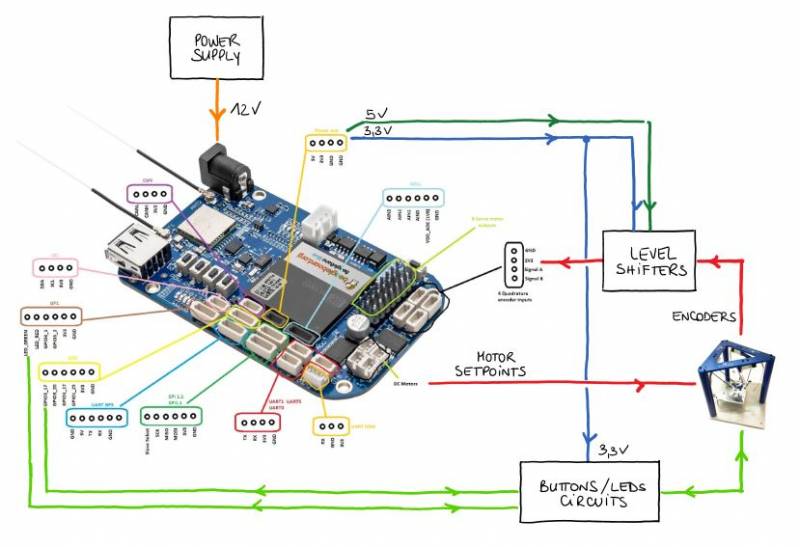
System Overview
LEDs and Buttons
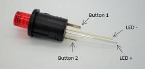
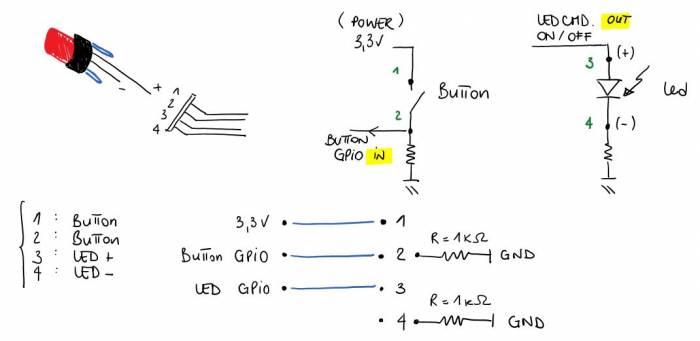
The robot is equipped with three buttons with leds. The buttons can be used to trigger actions. The leds are used to indicate operating states. The next picture shows the pin connections.
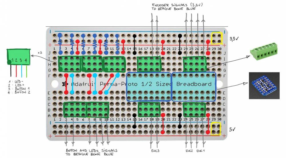
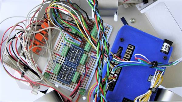
The buttons and leds must be connected to the breadboard (picture at bottom of this page) where the necessary resistors are placed and where the connectors to the Beaglebone blue board can be made.
| Connector | Pin assignment | BBBlue Channel | Connection |
|---|---|---|---|
| (GPIOx_y → x*32+y) | |||
| GP0 | GPIO3_17 | 113 | Green Button |
| GPIO3_20 | 116 | Green LED | |
| GPIO1_17 | 49 | Red LED | |
| GPIO1_25 | 57 | Red Button | |
| 3.3V | – | ||
| GND | – | ||
| GP1 | LED_GREEN | – | |
| LED_RED | 1 | evtl. Magnet | |
| GPIO3_1 | 97 | Blue Button | |
| GPIO3_2 | 98 | Blue LED | |
| 3.3V | – | ||
| GND | – |
Motors and Encoders
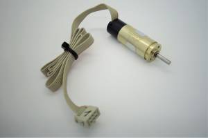
The Faulhaber Motors are equipped with a ribbon cable with connector.
Connections:
- Motor -
- Motor +
- GND
- Udd (5V)
- Channel B
- Channel A
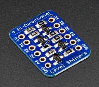
Motors receive an analog signal directly from the Beaglebone blue board. Encoders are supplied with 5V from the Beaglebone blue. The channel signals A and B of the encoder need a level shifter from 5V to 3.3V. We use a bi-directional level shifter of Adafruit: https://www.adafruit.com/product/757
This is one connection example for one motor, with encoder:
Breadboard
We connect all additional components to a breadboard of Adafruit https://www.adafruit.com/product/1609 and place it near the Beaglebone blue. Connections are shown in the following sketch:
