Control System
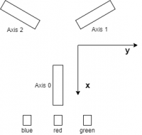
The coordinate system is as follows
In z direction, positive values move the TCP upwards.
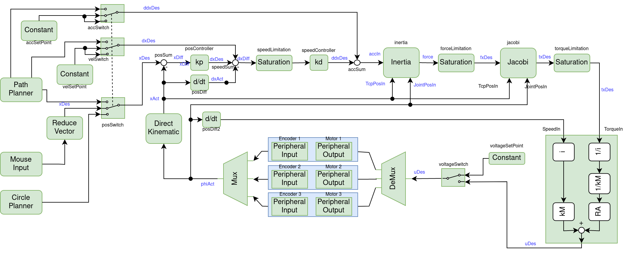
The figure below shows the complete control system for our delta roboter.

Inputs
Lets start with the blue box at the bottom center of the diagram. This box represent the motors including the gears and the encoders. The encoders are defined as Peripheral Input. This Peripheral Inputs are described in the HAL configuration file, see Hardware Abstraction Layer. To initialize the encoder inputs, you have to call the constructor of the Peripheral Input and add the respective signalId from the HAL configuration file as parameter, e.g.
eeros::control::PeripheralInput<double> enc1("enc1");
If the HAL is configured correctly, we get the current position in radian of each encoder. Next, the Mux collects the three encoder values and puts them into an AxisVector. AxisVector is defined as
using AxisVector = eeros::math::Matrix<3, 1>;
The mouse delivers a signal with four dimensions. As we do not use the fourth dimension (additional wheel would be necessary) we have to reduce the mouse signal to three dimensions with a special block. At the same time this block swaps x and y axis in order to adapt to the axis setup of the robot.
Kinematic
The Direct Kinematic converts the position of the motors into cartesian coordinates of the TCP (target center point). The output now contains the x, y, z value of the TCP.
Setpoint
Now we switch to the left of the diagram. We have three possible sources for the setpoint.
- The
PathPlanner, as the name says, plans the path to the next point. This is used for moving the robot from point A to point B. - The
CirclePlannermoves the robot in a circle with a given radius and speed. - The
Mouse Inputgets the movement of the mouse. We use this block to manually control the Delta robot. The output of theMouse Inputis an vector with 4 entries. We must reduce it to 3 containing x, y, z.
You have to make sure, that the path planner delivers a path with a acceleration and velocity which can in fact be achieved by the robot. If not, the arm might move in unpredictable ways. That is, moving from e.g. 0/5 to 5/5 must be made in a straight line.
Controller
The position of the TCP is controlled by taking in the setpoint (see above) and adding planned velocities and accelerations. The resulting total acceleration is then fed into the block 'Inertia' which - through Newton's law - calculates the resulting force. This force is still in cartesian coordinates and has to be translated into torques applied to each of the three motors.
Motor Model
As our board cannot only control voltages fed to each motor, we must use a motor model to calculate these voltages. The block 'Motor Model' gets the actual speed and the calculated torque as input, and outputs the desired voltage for each motor. We must also take the gear into account. The speed is reduced by the gear ratio while the torque must be multiplied with the same ratio. The following equation holds
U = kM * w + I * RA + dI/dt * L
with I = M / kM and dI/dt * L beeing very small with our motors and accounting for the gear i we get
U = kM * w * i + M * RA / (kM * i)
Outputs
The drive signals to the motor are of type PeripheralOutput. They are described in the HAL as well.
eeros::control::PeripheralInput<double> mot1("motor1");
The block 'voltageSetPoint serves for the initializing of the encoder when homing. It drives the motors with slow speed into a mechanical stop. This block is no longer used after reaching Safety Level systemReady.

