Delta mounting instructions
1. Part list
2. Assembly instructions
Within this document you can find the assembly instructions according to the new low cost delta robot.
2.1 Lower arms
- Required manufacturing time: 6 days
- Number of components required: 6
- Required components (per lower arm):
- 2x drilled sphere
- 1x ø3mm CFK pipe
- 2x cube magnets
- Epoxy glue
- Gauge
Add the epoxy glue according to its package instructions and fill the sphere holes with it. Now press one sphere on each end of the pipe.
Place the lower arm into the gauge respectively the lower arm’s spheres into the drillings they belong to (fig. 2.1).
To prevent the glue from pressing away the spheres from the CFK pipe it is recommended to place a magnet on the bottom side of the gauge. The glue takes about 24 hours to reach its ideal dryness.
Before mounting the next arm unit please clean the gauge carefully from any glue remaining.
2.2 Upper arms
- Required manufacturing time: 4 days
- Number of components required: 3
- Required components (per upper arm):
- 1x upper arm motor interface (left)
- 1x upper arm motor interface (right)
- 4x cylinder pin
- 1x ø11mm CFK pipe (cut to 31.6mm length)
- 1x upper arm link interface
- 4x cube magnets
- 1x collar
- 2x steel sphere (non-drilled)
- Epoxy glue
- Plastic glue
- Gauge
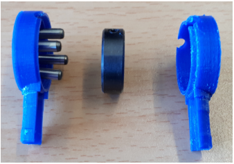
The next step is to mount the upper arm's motor interface (fig. 2.2).
Check first if both halves of the plastic cladding unit can be added so they fit together. If not, it is necessary to fix this issue by using a file to remove plastic print inaccuracies.
Add the epoxy glue according to its package instructions and fill the cylinder pin holes with it. Then coat a thin film of epoxy glue on the inside surface of the plastic cladding unit.
On the right part of the plastic cladding unit there is a drill hole for the engine shaft. At the same position on the left part of the plastic cladding unit, where the shaft lies against, the area must be kept free from any epoxy glue.
Now press the collar into one of the plastic cladding units (it does not matter into which one) and coat some epoxy glue on each of the four cylinder pin drill hole surfaces.
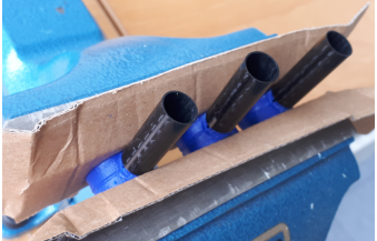
To make sure to keep the motor interface in the right position when the glue dries it is strongly recommended to press (but not to glue yet!) a piece of CFK pipe over the pipe plug. In addition it helps to use a mechanical clamp (do not use too much pressure!) to keep the plastic parts together (fig. 2.3).
Now attach the motor to the motor flange and the motor flange to the gauge. Push the upper arm motor interface onto the motor flange and fix it with allen screws. Now place the two steel spheres into the specified upper arm drill holes. To keep the steel spheres in place, add a cube magnet underneath each of the two steel spheres on the downside of the gauge. Now press each of the remaining two cube magnets into the belonging gaps on the upper arm interface. If necessary they can be mounted by adding some glue. Now glue both of the interfaces and the CFK pipe together (follow the safety instructions on the glue’s package instructions for working in closed rooms!). Use the gauge according to fig. 2.4 to make sure the upper arm’s precision as reliable as possible.
2.3 Delta robot
- Required components: All remaining parts
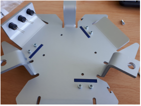
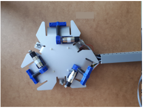
Mount the three push buttons and the three motor flanges (M3x10) onto the base plate according to fig. 2.5.
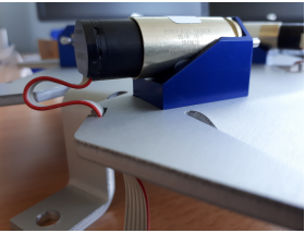
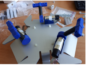
Mount each motor onto a motor flange (M2x5).
Insert the motor cable carefully into the cable route (fig. 2.6).
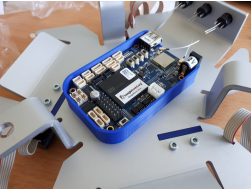
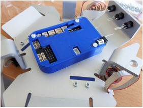
Now put the beagle bone blue board into its beagle bone case and align it by using the according drilling holes on the base plate (fig. 2.7a). According to fig. 2.7b, make sure to fix the shown corner first (M2.5×25).
Then add the case’s top cover and fix the remaining three corners (M2.5×25) according to fig. 2.8.
Now mount the three upper arms (fig. 2.9).
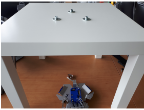
Feel free to mount the base plate according to its design on a surface of your choice (for this specific project there was an IKEA LACK table being used (fig. 2.10)).
It is recommended to finish the cabling work before mounting the base plate.
The whole cabling between the robot and a PC and its peripheries is meant to be hidden in a cable conduit (fig. 2.11).
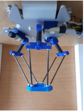
Now hang each lower arm into its belonging appliance and mount the tool platform (fig. 2.12).
Motors, push buttons and flat-band plugs have to be mounted to the voltage distributor (fig. 2.13).


